Drive Systems in Precision Gimbals
This article discusses constraints in designing drive systems for gimbal systems and proposes some of the latest generation engineering solutions in direct drive motors, encoders and slip rings.
November 12, 2024
.png)
Design constraints in gimbal construction
Gimbals are commonly used for electro-optics, satellite communications, laser pointing, LIDAR, movie equipment and remotely controlled weapons stations. Designing gimbal drive systems is notoriously challenging for engineers. In part, this is due to the many, often conflicting, requirements for precision motion control, reliable operation and tight limits on space, weight and cost. Recently, with more frequent use of battery power, we can add the requirement for low power consumption. Some other constraints are not obvious, including the need for:
- Smooth motion control at very low rotation speeds when tracking distant moving objects.
- Low weight for equipment mounted high on a boat or ship to avoid affecting stability.
- Low profile to avoid impacting the aerodynamics of manned or unmanned aircraft.
- Tight control of angular velocity and position regardless of the host equipment’s potentially rapid changes in roll, pitch, and yaw.
- Silent motion in camera and video gimbals.
Such constraints are common with gimbals (2-axis systems – usually azimuth and elevation) systems and frequently also apply to pedestal systems (1-axis system, usually azimuth - such as marine radar).

Traditional drive systems in gimbal and pedestal design
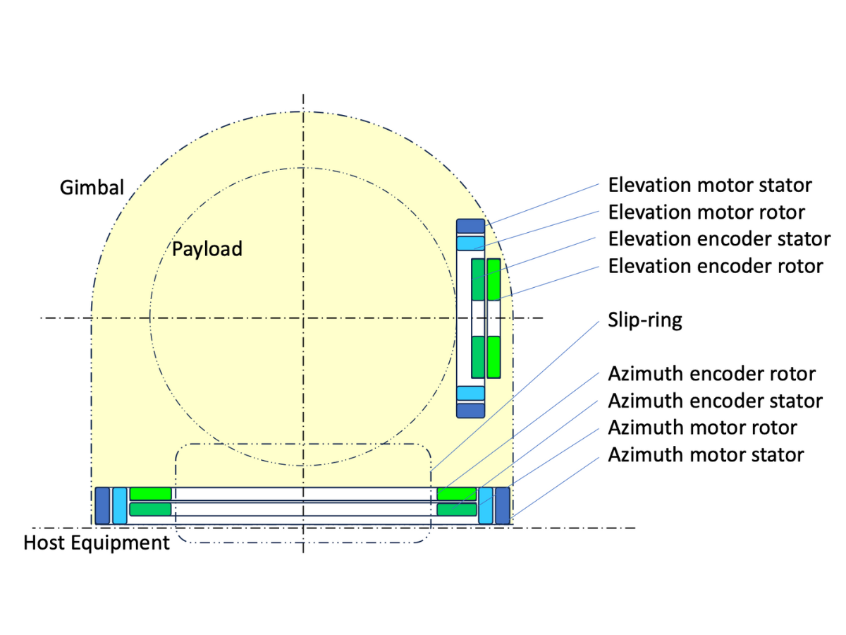
We can consider a gimbal’s drive system in 5 main elements:-
- Motors – one for azimuth and one for elevation axes
- Encoders – one for azimuth and one for elevation axes
- Slip rings – often only in the azimuth axis given limited rotation of elevation axis
- Servo drive – to receive position/speed signals from the encoders and to supply the required power to the motors typically via the slip ring.
Traditionally, a motor with torque and speed characteristics suitable for optimization through a reduction gear system was chosen for gimbal drives. This approach – typically referred to as an indirect drive - was partly driven by cost because direct drive motors (i.e. with no intermediate gearing) were too expensive or too bulky to deliver the required torque and speed.
Similarly, the traditional approach for encoders was to use a resolver for harsh environments (most notably aerospace and defense applications) or an optical encoder for less severe, indoor environments. Typically, position and/or speed were inferred by measuring at some point in the mechanical power / gear transmission to provide incremental speed signals and absolute position signal. Again, the approach was partly cost driven because encoders with large bores were not widely available or too expensive to consider.
Challenges with indirect drives
The geared, indirect approach introduces multiple challenges including:-
- Backlash and position inaccuracy - Gears inherently introduce backlash – leading to inaccuracies in position feedback, especially when the direction of movement reverses.
- Latency reduced responsiveness - In indirect systems, the encoder reads the position of a gear or motor shaft, not the gimbal’s output. This introduces latency and can lead to delayed responses in precise motion control.
- Increased accumulated errors and calibration challenges - Indirect measurement systems suffer from accumulated errors or tolerance stack up due to gear wear, thermal coefficients and backlash. Over time, these errors typically increase and may require periodic recalibration.
- Mechanical wear, friction and noise - Gears wear, especially in high duty cycle applications. As gears wear, backlash increases, leading to greater system hysteresis and inaccuracy. Gears also add friction, which not only reduces efficiency but generates noise and potentially vibration. Noise and friction can interfere with sensitive applications, such as videography, where smooth, silent operation is critical. Friction in gears can also hinder fine motion control, affecting the smoothness and accuracy of the movement especially at low speeds. Friction can be minimised by lubrication, but this can require more regular service or maintenance.
- Thermal Drift - Mechanical components in the drive will be subject to thermal expansion/contraction as operating temperature varies. These small changes alter the effective position of the gimbal without necessarily altering the encoder reading.
- Decreased reliability – simply put, the more mechanical parts, the greater the effect on mean-time-between-failure–particularly in harsh environments.
- Increased weight and physical volume.
A modern approach to Gimbal Drive Systems – Direct Drive

A more recent approach in gimbal design is to use direct drive and direct measurement and this largely eliminates the issues caused in traditional gimbal drive systems. The change has been enabled by two fairly recent developments. First, a step change in direct drive motor technology, enabling substantial torque generation from thin annular geometries - and at a more realistic price point. Such motors are commonly referred to as torque motors.
.png)
The change in motor size, weight and power largely derives from recent changes to the way in which motor windings are produced. Leading this new wave is Alva Industries whose ironless, slotless motors (see SlimTorq™ Motors) are made using FiberPrinting™. This technology maximizes copper fill factor with non-skewed stator windings which, in turn, result in a motor-constant and torque density rivalling even the best slotted motors. With such high copper fill factors and the flexibility to produce custom shapes, Alva’s motors offer best-in-class performance for a given size and weight.
The removal of the iron-teeth in Alva’s SlimTorq™ motors also results in a stator and rotor that’s surprisingly thin and light. Precision SlimTorq™ torque motors are slotless which means they offer virtually zero cogging and negligible torque ripple – making them ideally suited to precision gimbal applications. The SlimTorq™ range is offered in two versions: the Lite version, which is optimized for weight-sensitive applications and SlimTorq™ Max which is optimised for maximum performance i.e. as high as possible torque and motor constant within the space envelope.
A modern approach to Gimbal Drive Systems – Direct Measurement
The second change that has enabled the direct approach is position encoder technologies based on thin annular geometries and – as with direct drive motors - at a more realistic price point. whereas the traditional approach, especially in aerospace and defense, was to use resolvers, this modern direct measurement approach has various technologies to choose from including optical, capacitive, inductive and magnetic position sensing techniques.
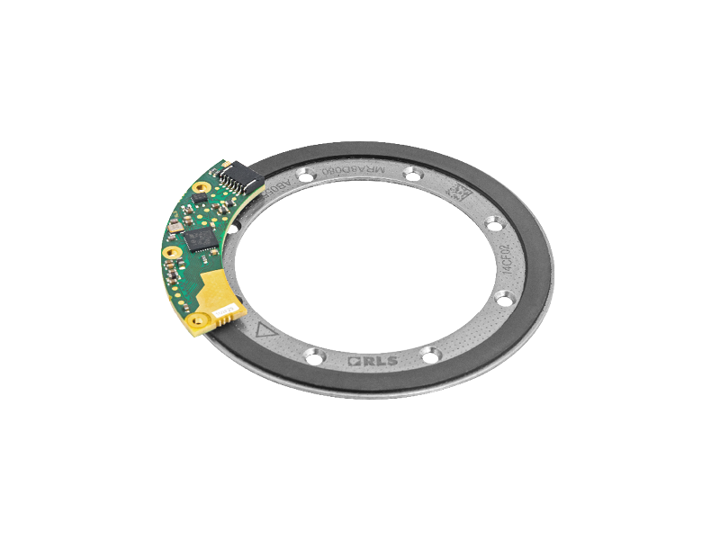
Magnetic encoders are a popular choice for gimbals, as they offer an attractive balance of price and performance point

in a convenient format with low axial height and a large bore. Measurement performance includes resolutions of >20bits and reliable operation in wet or dirty environments.
Advantageously, they accept a DC power supply and generate digital output signals – thus avoiding any potential degradation of the signals through the slip ring.
The compact form is of particular value to design engineers struggling to fit drive system components into a restricted space envelope. Given the slim, annular form of the motors and position encoders, sip rings, optical fibres, cables and mechanical parts can be routed through the centre of the device.
Nicolas Giraudo
Chief Commercial Officer
Fossegrenda 1, 7038 Trondheim, Norway

All rights reserved ©2025