The scaling rule for frameless motors - Diameter, Length, & Torque: A practical design guide
Designing a frameless motor is about balancing torque, space, efficiency, and thermal limits within the constraints of the application. While torque increases linearly with motor length, it scales with the square of the diameter - making diameter one of the most effective ways to increase torque density. But selecting the right motor is not just about maximizing size or current. The best designs come from understanding how geometry, cooling, electromagnetics, and system integration work together to achieve the required performance efficiently.
May 21, 2026
.png)
Why It Matters
In a lot of applications such as robotics, gimbals, and medical devices, torque defines performance. At the same time, designers deal with tight space constraints and strict weight limits.
That’s exactly where frameless motors shine. Frameless motors allow for motor integration directly into the mechanics of the device and use space more efficiently. But if the design is not well thought through, those advantages are making less of an impact. Getting the needed torque without oversizing, overheating, or overcomplicating the design is the goal.
Practical Design Considerations
Torque Density vs. Size Constraints
One of the biggest levers of motor design to achieve high torque is motor size, especially diameter. If more torque is needed, increasing diameter, increasing length, or increasing current are the available alternatives. These are not equally effective. Increasing diameter tends to impact much more than the torque achieved, compared to simply making the motor longer or increasing current.
Torque ∝ D𝐷2 x L
No mechatronic design allows unlimited space for the motor. When there are constraints on space, it helps to think carefully about how that space is used efficiently. A small increase in diameter can go a long way. If the choice is possible, it is usually better to grow outward rather than just stretching the motor longer.
Why do Manufacturers offer longer motors rather than bigger diameters?
Frameless motor manufacturers tend to offer on their portfolio a limited number of Diameters, while adapting the so called “stack length” and offering multiple options of length of the same motor designs. This is driven by the fact that changing the diameter of slotted designs requires significant investments in design, machines, and tooling. This is different for slotless motors, since the outer diameter can be changed with a similar amount of effort to the length of the motor, even though the manufacturing methods have been traditionally less automated and more expensive. This combined with a reduction of torque compared to slotted designs has kept their utilization in torque driven applications to specific niche markets. Alva’s FiberPrinting™ has changed this paradigm entirely, where this is now possible.

Current & Thermal Limits
On paper, torque scales with current, so it is tempting to push more current through the motor to get more torque. This approach has a big limitation: heat. Frameless motors depend on your surrounding structure to remove heat. The housing, mounting surfaces, and materials play an important role in how much torque it can be produced with a given motor. Things that matter in this regard include how well the motor is bonded to the housing, what materials are used in the mechanics, and whether the motion profile is a continuous duty or short peak accelerations.
A design that looks great electrically can fall apart thermally if heat cannot escape. In most real systems, torque is not limited by the motor itself. It is limited by how well heat can be removed from it. Among other considerations, the housing you have where the motor sits inside needs to be carefully analyzed. Does it have enough thermal mass to absorb heat from the motor, and does it have enough surface area to dissipate it into the environment? Is airflow across the housing (active cooling) required? Is it submerged in water or other liquids? Is active water-cooling available? Is just cutting heat sink fins into the housing enough?
Changing Electromagnetics
Another approach is to change the motor windings, essentially reshaping its magnetic field. Adding more turns makes the field stronger for the same amount of current, so the motor can pull harder, and it can be run at a lower voltage to get the same speed. The downside is that extra wire means higher copper resistance, which turns into more I²R losses and can raise the motor’s temperature unless thicker conductors are used. If the number of turns is reduced, the field weakens; the motor can then run at higher speeds with less back‑EMF, but it will need a higher voltage to produce the same torque, and the copper cost goes down. Smoother winding patterns cut torque ripple and improve thermal performance, while a tighter winding can squeeze more inductance into a smaller package, changing the motor’s speed‑torque curve. These changes are similar independent if the diameter or length of the motor are changed, but they are relevant to understand the tradeoffs available when a geometry needs to be selected.
Electrical Changes with Diameter
Increasing a motor in diameter typically means a higher number of magnetic poles. Changing the number of magnetic poles has a big impact on a BLDC motor’s speed and torque. In a BLDC motor, the mechanical speed that a given drive frequency can achieve is inversely proportional to the number of pole pairs: doubling the pole count halves the maximum mechanical speed for that same electrical frequency. The payoff is that the torque constant increases roughly in proportion to pole count, giving more torque per A, and the motor can be finely controlled at low speeds because there are more electrical cycles per mechanical revolution. However, a higher pole count also raises the back‑EMF constant, so for a fixed drive voltage the motor reaches its maximum speed at a lower rpm. On the plus side, more poles smooth the torque ripple and make the back‑EMF waveform more sinusoidal, reducing harmonic losses and improving efficiency. Engineers therefore choose the pole count to strike the right balance between attainable speed, torque density, size, and efficiency for the intended application. In short, if torque is the main parameter of the motion profile and application, increasing diameter is potentially the best approach, especially on direct drive applications. However, if speed is required, like in the case of many geared applications, increasing the length may be more sensible, as discussed in the next section.
Gearing & Integration
In certain applications, the easiest way to get more torque may not be to focus on motor design only. If the application allows for a geared actuation concept, adding a gear reduction allows torque multiplication at the output, and to run a smaller motor at a more efficient speed. Of course, this approach requires some trade-offs. Adding a gear means adding complexity, and depending on the gear type, backlash or loss of overall efficiency may be potential consequences. When frameless motors are paired with well-integrated gearing, such as harmonic or planetary systems, they can be extremely effective.
A Simple Design Workflow
When working through a design, having a clear process helps keep things grounded.
1. Starting with Torque & Speed
Before anything else, the needs of the application need to be defined. This includes continuous torque, peak torque, and the required speed range. This gives clear target for the motion system.
2. Thinking About Thermal Limits Early
It does not have to be perfect, but a rough idea of how much heat the system can handle is a great second step. Looking at available cooling, whether passive or active, the available surface area, and the materials and mounting approach will save valuable time later. This helps to understand how much current, and therefore torque, can be realistically produced by the motor.
3. Deciding What are the Design Priorities
At this point, what matters most must be defined. Optimizing everything at once is a recipe for failure. Recognizing the limitations, space, torque, or thermal performance will allow you to focus on the right objectives. Once the bottleneck has been identified, decisions become much easier. E.g. if space is fixed and limited, focusing on diameter and cooling makes sense. If torque is fixed, adjusting motor size or adding gears may be the best option. If thermal limits dominate, managing current and duty cycles are more relevant.
4. Compatibility with electronics & other parts of the system
After the mechanical and physical fit of the system has been chosen, the last part to ensure a fully optimized system is to make sure the motor driver can support the motor selected. This includes not only electrical frequency and matching the speed requirements with the number of poles, but also switching frequencies, voltage and current required to achieve the motion profiles.
Examples
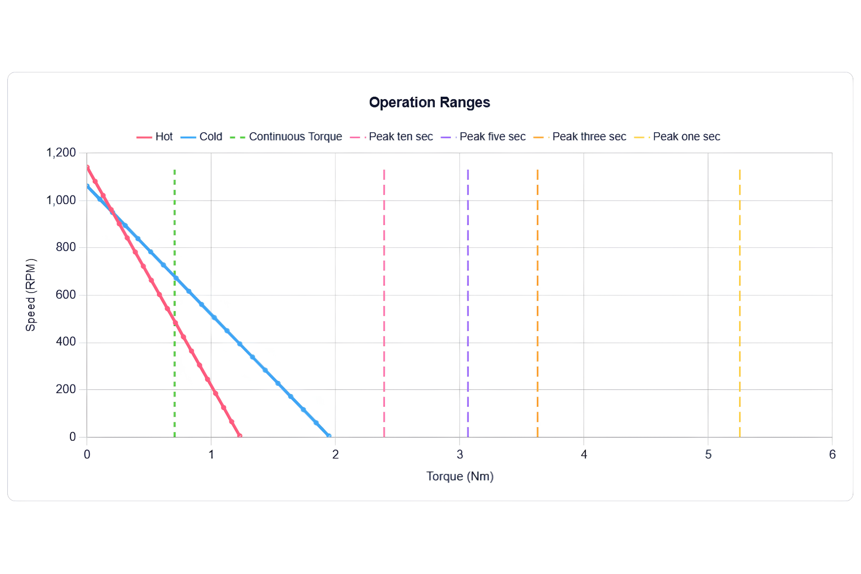
Looking at the first example below, you can see the concept of D2L at work. A ⌀105mm x 17mm motor has the same working potential as a ⌀60mm x 50mm motor. They share the same continuous torque level, and similar operation range. The difference is that the 105-17 is only 250 g heavy, while the 60-50 is 370g. Using this confirmation of the concept, this shows that selecting a motor goes beyond performance alone. The design workflow discussed in previous segments should be taken into consideration.

.png)
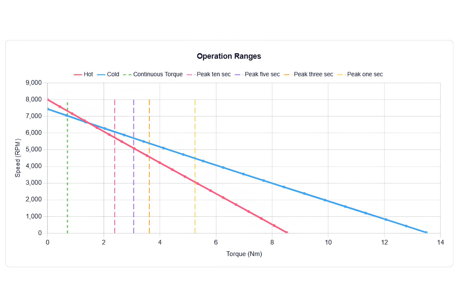
The second example below shows an Alva Motor STM-75-20-L with two different winding configurations. The first one shows the curves of the motor with a Star configuration and 8 series of turns. The second one is a Delta configuration, with 2 Series of turns. It can be observed that keeping the physical shape of the motor the same, when adjusting the number of turns of copper in the motor and their sequencing order, you can adjust the motor parameters. Not only the available operation range, but also how much current it may take to provide the same performance. Both windings belong to the same physical footprint of motors. Both run at 20 V, yet the performance is vastly different. When looking at the electrical details, in short, the 8Y winding draws a max current of 3 A (for the continuous operation), while to get the increased performance out of the 2D it draws approximately 21 A. This is where selecting the motor that not only fits the torque/speed outputs you need but also the electrical and thermal constraints that exist on your platform.
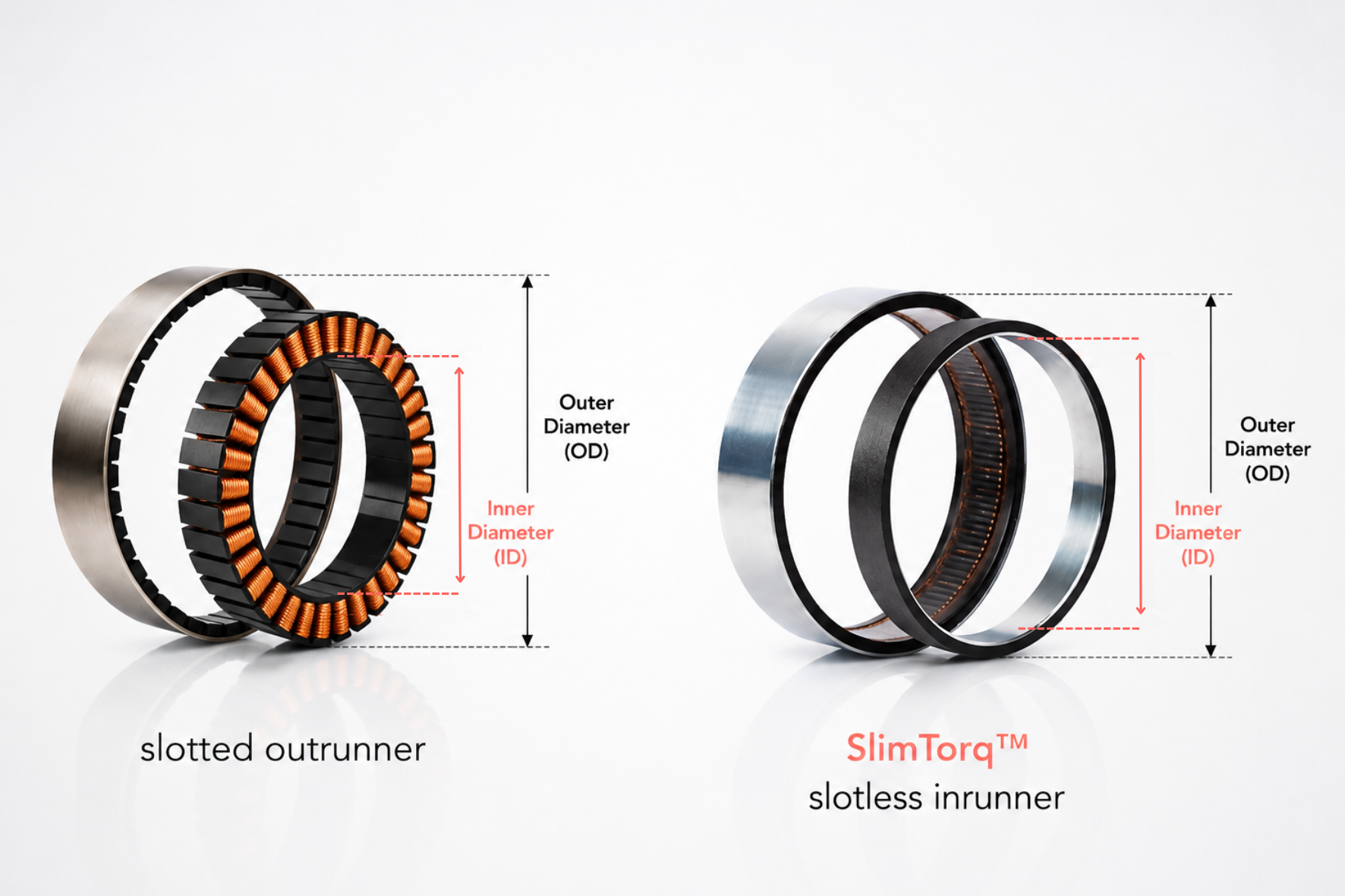
Keep in Mind, Internal Diameter and Outer Diameter
When reading a data sheet of a particular frameless motor series for a torque driven application, the priorities are to define if the physical envelope of the motor fits the design and if the performance of such motor is enough for the application, i.e. Outer Diameter, Length and Torque. However, a very important and sometimes overlooked aspect of such motor is the Internal diameter. Overlooking the internal diameter may sometimes require opting for outrunners, which in many cases increases the complexity of the system, especially on mounting and heat dissipation. Therefore, when considering the volumetric torque density of a motor, not only does the volume defined by the external dimensions need to be analyzed (L*π*OD2/2), but the volume available by the internal diameter needs to be subtracted from it (L*π*ID2/2). A very thin motor may allow for extremely compact designs while getting the same torque outputs.
Final Thoughts
Getting higher torque outputs of a frameless motor is not about increasing current (only). It starts with designing smarter around it. In many cases, the biggest gains come from aspects that are not obvious at first, such as a slightly larger diameter, a better thermal path, or a well-chosen gear ratio in geared applications. When a motor is thought of as part of a larger system instead of a standalone component, designs are not only more powerful, but also more efficient and reliable.
The new approach of Alva Industries to manufacture slotless frameless motors with a comparable torque output to slotted motors has opened design possibilities that were not possible in the past. With FiberPrinting ™ Alva Industries is able to customize motors for specific applications and operation points. Real design flexibility on motor design is unlocked with TorqStudio, Alva allows engineers to set their minds free at designing and simulate what a custom diameter, length and winding can do for their application keeping the design freedom.
If you are interested in learning more about our motors and technology, please reach out to us here.

All rights reserved ©2025