Outrunner and Inrunner Topologies Explained: Torque Leverage, Inertia and System Boundaries
Selecting the optimal brushless motor architecture - outrunner or inrunner with large through-holes - defines system limits. Outrunners maximize air-gap radius to generate higher static torque, while inrunners reduce inertia for superior dynamic bandwidth and thermal dissipation. This article analyzes the physical principles and geometric trade-offs that guide motor selection in advanced mechatronics.
March 17, 2026
.png)
Outrunner Vs. Inrunner: Physical Differences
.png)
Brushless motors are categorized into two distinct designs: inrunner and outrunner. The defining difference is that an outrunner’s outer housing rotates around an inner structure. Even in integrated mechatronic systems where the motor is not visible, this architectural distinction remains fundamental. The rotor and stator assembly differences are as follows:
Rotor Assembly:
- An outrunner's magnets are mounted on the inner surface of the rotor, a thin external rotating shell, or “can”. This configuration maximizes the torque radius by placing the active air gap at the maximum distance from the rotational center. Since rotation is concentrated at the outer periphery, components like ring gears or pulleys can be attached to the motor’s outer shell.
- Inrunners feature magnets affixed to an internal rotating body, which concentrates mass near the rotational axis and diminishes the effective air-gap radius. This reduced radius minimizes rotational inertia and allows for smaller bearings, significantly enhancing rotational dynamics. This topology is ideal for traditional shaft-driven linkages.
Stator Assembly: - An outrunner's stator is a stationary electromagnetic core mounted on a central structure.
- An inrunner's stator is a stationary electromagnetic element mounted inside the outer cylindrical housing

Electromagnetic Differences and Radius-Dependent Leverage: an Outrunner Advantage
From an electromagnetic perspective, motor torque is determined by the interaction of the air-gap radius, active axial length, and electromagnetic shear stress. This relationship is critical when comparing architecture, as geometric scaling directly dictates torque density, efficiency, and continuous performance. The governing torque relationship is:
Torque T = 2π·σs·r²·L(Nm)
where:
r is the effective air-gap radius (m)
L is the active axial length (m)
σs is the electromagnetic shear stress (N/m²)
Because torque is proportional to the square of the radius (T ∝ r²), even marginal increases in air-gap diameter yield substantial gains in mechanical advantage. The primary differentiator is geometric leverage:
- An outrunner utilizes the maximum available radius within a specific outer diameter (OD) to maximize the torque arm. This yields a higher torque constant (Kt) per unit of current, reducing the ohmic losses required to maintain a static holding position.
- In contrast, the inrunner inherently possesses a smaller torque arm because the magnets sit closer to the center. To match the same torque output, the motor must either increase axial length or run with more current. In space-limited or thin motor designs, this results in higher electrical loading and heat, often creating a thermal limitation.
Back-Electromotive Force (Back-EMF):
- Outrunners facilitate higher magnetic pole counts and greater Back-EMF per revolution, resulting in a larger voltage constant (Ke in V/kRPM). This phenomenon stems directly from the outrunner's increased diameter. Consequently, high Ke outrunners are frequently employed in direct-drive scenarios to leverage this inherent advantage.
- Inrunners, within a standardized size class, typically demonstrate a smaller voltage constant Ke. These configurations are frequently optimized for higher-speed operation and can be combined with gear reduction where application-level torque multiplication is desired.
Inertia and Dynamic Response: An Inrunner Advantage
Torque alone does not determine dynamic motion performance. Rotational inertia (J) represents a body’s resistance to changes in angular velocity. Higher inertia requires more torque to accelerate or decelerate, which inherently slows system responsiveness. Angular acceleration (α) dictates dynamic system bandwidth and response time.
Rotational inertia: J ∝ m·r² (kg·m²)
Angular acceleration: α = T / J (rad/s²)
where:
m is the rotor mass (kg)
r is the effective air-gap radius (m)
For all radial flux motors, torque scales with the square of the air-gap radius (T ∝ r²). While outrunners provide superior static torque leverage due to their large radius, the geometric reality of placing mass far from the rotational axis heavily penalizes their dynamic responsiveness. Because different motor topologies dictate vastly different physical dimensions and materials for a given motor footprint, a direct comparison requires looking at exactly how angular acceleration scales with size.
- Outrunners: For a given footprint, outrunners maximize torque leverage through a large effective air-gap radius, but they rely on a heavy back iron. This housing mass (m), simplified as a thin shell, scales linearly with its circumference (m ∝ r), causing rotational inertia to scale to the third power (J ∝ r³). Therefore, angular acceleration scales inversely with the radius (α ∝ 1/r). This massive absolute inertia decreases the system's angular acceleration, making outrunners less suitable for high-frequency dynamic motion.
- Slotted inrunners: The rotor spins centrally, restricted to a much smaller absolute diameter by the surrounding bulky stator teeth. Because these rotors require a solid steel core to carry magnetic flux, they are not modeled as thin shells; their mass scales quadratically (m ∝ r²), and their rotational inertia scales steeply to the fourth power (J ∝ r⁴). Consequently, acceleration scales inversely with the square of the radius (α ∝ 1/r²). Despite this severe scaling penalty, an inrunner concentrates its mass so much closer to the rotational axis that the drastic reduction in absolute inertia far outweighs the reduction in the torque arm. This yields significantly faster response times and higher closed-loop bandwidth, favoring dynamics over static torque.
- Slotless inrunners: (Like Alva's SlimTorq™) eliminate bulky stator teeth, allowing the internal rotor to expand closer to the motor's outer diameter to capture outrunner-like magnetic leverage. Furthermore, a self-shielding Halbach array eliminates the need for a heavy steel flux-return yoke, allowing for an ultra-lightweight aluminum rotor sleeve. This topology maintains favorable thin-shell scaling (J ∝ r³, α ∝ 1/r) but drastically reduces the absolute baseline mass (m). The mass reduction dominates the 1/r penalty, resulting in a high T/J ratio, delivering high torque and angular acceleration.
Thermal Management: an Inrunner Advantage
Continuous motor torque is fundamentally limited by the stator’s thermal dissipation. Safe winding insulation temperatures and magnet stability dictate allowable current and torque output. Slotted machines face peak torque limits due to magnetic saturation in stator teeth. In slotless designs, where saturation is negligible, transient peak torque benefits directly from enhanced application-level cooling.
Thermal resistance: Rth ∝ 1 / (reff·L)
where:
reff is the radius of the thermally dissipating surface (mm)
L is the active axial length (mm)
Assuming surface-limited cooling, a motor's thermal resistance to the ambient environment (Rth, measured in °C/W) scales inversely with its heat-rejecting surface area (Rth ∝ 1 / (reff·L)). Because heat dissipation capacity scales linearly with this radius, architecture dictates continuous performance.
Thermal Management:
- Inrunner architecture is superior for high continuous torque because thermal energy rejects radially outward. Since the stator - the primary heat source-is bonded to the outer housing, energy dissipates efficiently via conduction to the environment or liquid cooling.
- Outrunners instead retain heat within a stationary core, creating a "thermal island". This necessitates complex cooling or severe torque derating to prevent insulation failure. Furthermore, heat conducted into the small shaft and bearings can compromise lubrication and mechanical reliability.
Mechanical Integration and System Constraints
Frameless architectures optimize system design, offering freedom to define rotation, torque transfer, and force flow through integrated components.
Through-hole Capability:
Historically, outrunners were preferred for large apertures since their torque radius is independent of the through-hole. Conversely, expanding a slotted inrunner's through-hole reduces space for stator teeth and windings, causing severe torque penalties. FiberPrinting™ slotless technology redefines this paradigm: by eliminating iron teeth and achieving up to a 60% Copper Fill Factor, SlimTorq™ motors enable ID/OD ratios up to 86.2%. This allows routing slip rings, optics, and cabling centrally without the performance or thermal penalties of conventional designs.
Aperture Efficiency: SlimTorq™ Lite Series
The following data demonstrates the aperture capability across the SlimTorq™ Lite (L) portfolio:

Bearing Integration and Load Paths:
Traditional inrunners use central bearings to minimize linear speeds. Large-aperture slotless motors - both inrunner and outrunner - can utilize large-diameter, thin-section bearings for superior moment load support. In rim-drive thrusters, an inrunner rotor with a large enough through-hole can attach directly to the propeller rim. This removes the central shaft and reduces drag while leveraging the architecture's inherent thermal advantages.
Environmental Protection:
- Inrunner architecture naturally supports enclosed designs where a stationary outer shell shields the air gap from contaminants like moisture or particulates. Adding shielded bearings further enhances protection.
- Outrunners often remain open to facilitate stator cooling, exposing the air gap to particulate ingress and degradation. While secondary large diameter seals can be added, they increase friction and reduce efficiency.
.png)
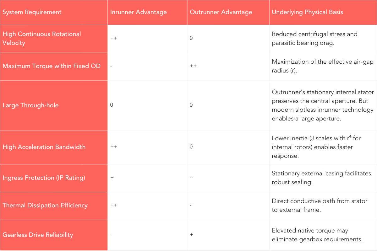
Architectural Selection Matrix
An appropriate architecture selection can be based on prioritized system requirements:
Slotless Inrunner Implementation
Historically, inrunners sacrificed torque leverage for dynamic response, but modern slotless designs eliminate this compromise via stator and rotor optimization. Replacing a slotted iron stator with a high-density non-skewed FiberPrinted™ stator increases the effective air-gap radius (r) within the same envelope. This expands the torque arm to improve leverage while maintaining low inertia and efficient heat dissipation. Additionally, Halbach-array rotors increase flux density without a heavy back-iron in the rotor, enhancing magnetic utilization while further reducing mass and inertia.
Conclusion
Outrunner and inrunner differences have been explained by radius-dependent constraints. The choice to use one type will enable or limit a motion control system.
- Outrunner solutions are best suited for high static torque. If the motor can also serve as a load-bearing structural component, these requirements can be well served.
- Inrunner solutions are ideal for systems optimized for speed and dynamic behavior, providing superior thermal management and high-frequency motion capabilities necessary for rapid positioning and stabilization.
These differences are narrowed by the advancements of slotless inrunner torque motors, which do not have the dynamic or thermal limitations of outrunners.
Evaluating real systems requires addressing application-specific trade-offs beyond basic topology. The referenced white papers analyze these in context, including thermal constraints in QDD actuators, saturation in slotted machines, and large through-hole benefits. By integrating electromagnetic, mechanical, and thermal factors, these documents define a system’s true performance and ownership cost.
---
References
Alva Industries A/S. (2025). *Slim2Real: SlimTorq™ powered AI actuators and QDD actuator design considerations*. Trondheim, Norway: Alva Industries A/S.
Alva Industries A/S. (2025). *Large through-hole diameter: Integration benefits in prosthetics and robotics*. Trondheim, Norway: Alva Industries A/S.
Alva Industries A/S. (2025). *Technical inefficiencies and total cost of ownership in precision gimbals*. Trondheim, Norway: Alva Industries A/S.

All rights reserved ©2025