Torque Saturation: How to properly Read Frameless Motor Datasheets
Selecting a frameless motor is about more than comparing torque values. This article explains how to correctly interpret motor datasheets by understanding continuous and peak torque, torque saturation, motor constants, winding configurations and drive limitations - helping you avoid common selection mistakes and choose the right motor for your application.
July 21, 2026
Selecting a frameless motor can be tough, by selecting the required torque, scanning the datasheets of motor suppliers, and choosing the smallest motor that meets the required torque. By doing this type of selection without considering more aspects discussed in this article, mechatronics designs fail to deliver the performance required. A datasheet is not a ranking table; it is a set of operating boundaries. Continuous torque, peak torque, torque constant and maximum speed describe different aspects of that boundary, often under very specific test conditions. They only become meaningful when interpreted together within the context of the complete motor-drive system. Want to evaluate motors based on your application requirements? Use Alva's Product Selector or request access to TorqStudio to compare motors under real operating conditions.
What is Torque Saturation?
Within its linear operating range, the torque of a permanent-magnet motor is approximately proportional to q-axis current:
T ≈ Kt × Iq
T = Torque in [Nm]
Kt = Torque Constant [Nm/A]
Iq = q-axis current [A]
This lets the control system treat current as a direct request for torque. Increase current by 20%, and torque should increase by roughly 20%.
That assumption becomes unreliable when the magnetic circuit saturates. In a conventional slotted motor, the stator teeth carry concentrated flux. At high current, parts of the iron can reach a point where additional current produces progressively less useful flux. The torque-current curve bends away from the ideal straight line, where saturation begins.
Torque may still increase, but less efficiently, while copper loss continues to rise with the square of current. A small additional torque gain can therefore carry a large thermal penalty. Therefore, peak torque should not be calculated linearly with Kt and current input as Kt describes only the linear region.
On the other hand, slotless motors have no stator teeth and avoid the same local tooth-saturation mechanism. Their torque-current relationship remains linear over a much wider range. The linearity does not mean that torque is unlimited. It means that temperature, magnet protection against demagnetization, mechanical constraints, or drive performance (current) are more likely to define the practical peak limit.
.png)
Limiting Factors to Torque
The electromagnetic saturation determines whether more current still produces proportional torque. The thermal conditions determine how long the losses can be tolerated. The electrical performance determines whether the required current can be supplied at a certain speed, given resistance, inductance, and back EMF. Finally, the drive power limit determines whether the inverter can supply that current and voltage.
A motor may be capable of achieving the required torque magnetically, but not continuously due to thermal conditions. Capable of reaching the torque at low speed, but not at the required speed. Or capable of reaching the torque theoretically in the datasheet, while the selected drive may not be capable of doing so.
Continuous torque is a thermal statement
Continuous torque is the torque a motor can produce for an unlimited duration without exceeding its permitted temperature under the stated cooling conditions.
Mounting interface, housing material, convective flow, cooling temperature and ambient temperature all affect the torque capability. A frameless stator mounted into a substantial aluminum structure conducts heat very differently from the same stator tested in a small housing. Both figures can be correct, but they are not comparable unless the thermal conditions are comparable.
Check the ambient temperature, housing or heat sink, cooling method and permitted winding temperature. Also check whether the value applies at standstill or at speed. Iron, magnet and eddy-current losses increase with speed, so continuous stall torque is not automatically available across the full speed range.
Peak torque is a time statement (and a thermal statement)
Peak torque describes a short operating event. It should always be paired with a duration and a starting thermal condition.
A motor starting at 20°C has a higher margin thermally than one already close to its continuous operating temperature limit. Peak torque depends heavily on duration. A longer peak puts more heat into the winding, so the allowed torque must be lower to stay within the motor’s safe thermal limit.
Peak torque must be read with peak current, current convention, duration, repetition rate, initial temperature and maximum winding and rotor temperatures. Demagnetization margin and drive capability also matter. A single large peak-torque number without these conditions is not enough for design work, as it might imply a very high current draw.
At speed, voltage becomes part of the same question. The drive must overcome back EMF as well as resistive and inductive voltage drops. A current that is easy to produce near standstills may no longer be achievable at high speed.
In TorqStudio, operating points can be evaluated using your application's torque, speed and thermal requirements, making it easier to understand how these parameters interact.
Motor Constants are related
There are four important constants that need to be understood and equally considered when selecting a motor. They are not all equally important for all applications, but they are related to each other as described in this section.
Need help converting motor constants or understanding their relationship? Explore Alva's free Electric Motor Toolbox for engineering calculators covering torque, speed, voltage, motor constants and more.
Torque constant, Kt
Kt links current to torque in the linear range. The units in which the constant is expressed mean something concrete. Nm/Arms is not directly interchangeable with Nm/Apeak, and phase-current values should not be mixed with line-current values. Nm/Arms measures how much torque the motor produces per Root Mean Square (RMS) amp, while Nm/Apeak means the same but for the peak amp of current.
Motor constant, Km
Km relates torque production to copper loss:
Km = Kt / √R
The resistance convention must match the Kt convention. When Kt uses RMS q-axis current and resistance is line-to-line, the corresponding three-phase resistance factor must be included.
Km is useful because it indicates how much torque a motor produces for a given copper-loss level. It is most informative at low speed and stall. It is not a complete high-speed efficiency metric, where iron, magnet, and eddy-current losses also matter.
Voltage constant, Ke
Ke describes the back EMF generated per unit of speed. A higher motor Ke uses more of the available bus voltage at a given speed, so it is closely linked to winding choice.
Checking Ke against maximum speed, usable drive voltage, and the margin required for current control is essential. Designing directly to the nominal DC-bus voltage leaves no room for resistive drop, inductive drop, modulation limits or control margin.
Resistance and inductance
Resistance determines copper loss and rises with winding temperature. A value measured at 20°C is lower than the resistance during hot operation.
Inductance affects current ripple and current-loop bandwidth. Slotless motors often have low inductance, supporting fast current response and therefore sometimes requiring a higher switching frequency, suitable filtering or tuning. A drive selected only by current rating may still be the wrong choice.
Winding Configuration Selection
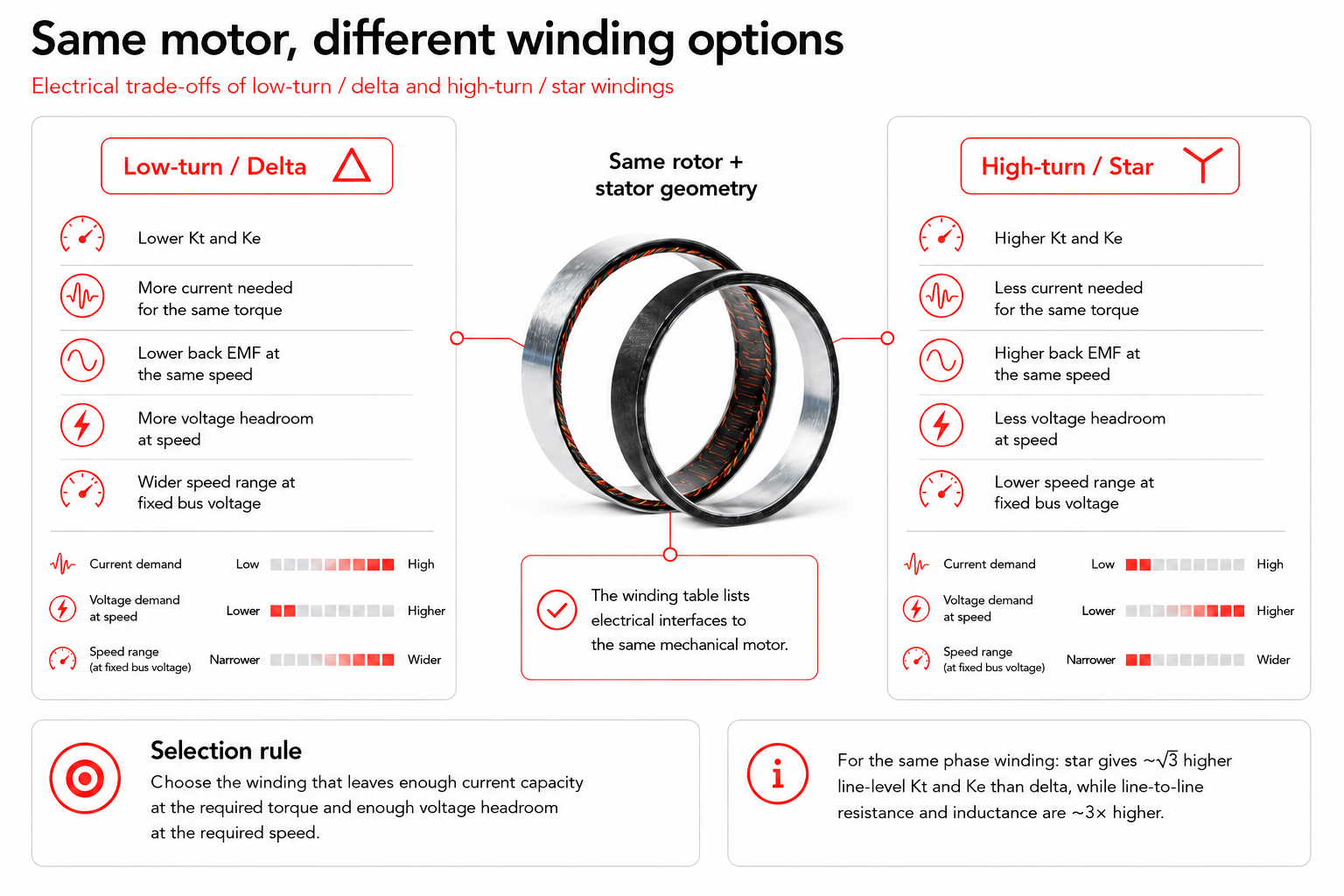
The winding configuration is a list of electrical interfaces to the same rotor and stator geometry.
More turns generally give higher Kt and Ke. The motor needs less current for the same torque but generates more back EMF at the same speed. At a fixed bus voltage, its speed range is therefore lower. Fewer turns do the opposite: lower Kt and Ke, higher current demand and more voltage headroom at speed.
Star and delta shift the same trade-off. For the same phase winding, star gives approximately √3 times the line-level Kt and Ke of delta, while line-to-line resistance and inductance are approximately three times higher.
The correct winding leaves enough current capacity at the required torque and enough voltage headroom at the required speed.
The three most common mistakes
The three most common mistakes at reading a motor datasheet are:
1. Comparing peak torque with continuous torque
Compare continuous with continuous under similar thermal conditions and peak with peak at the same duration and starting temperature.
2. Treating continuous torque as a universal comparison rule
Continuous torque belongs to a motor-plus-cooling arrangement. When cooling assumptions differ, the values need to be adjusted and supported by a thermal model.
3. Ignoring the drive (electronics)
The servo drive must supply the RMS and peak current, provide enough voltage at the required speed, and control a potentially low-inductance load. It needs a suitable switching frequency for low-inductance motors.
Alva FiberPrintingTM enables linearity
With Alva FiberPrinting™, torque scales predictably with current because the motors are slotless and not limited by torque saturation. This makes the datasheet easier to use: Kt directly shows how much torque is produced per ampere, simplifying motor sizing, drive selection, and peak-torque checks.
Explore the SlimTorq™ product family to see how FiberPrinting™ technology enables predictable torque performance across a wide operating range.
Final thoughts
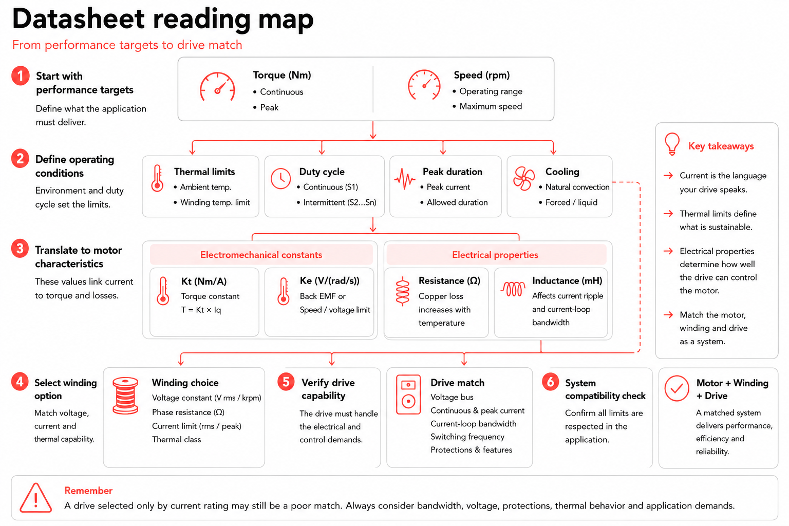
A frameless motor datasheet becomes useful when it is read horizontally, not vertically. Torque, current, duration, temperature, winding, voltage, and drive capability belong to the same operating point.
The useful question is not which motor has the largest torque number. It is whether the complete motor-drive-thermal system can produce the required torque, at the required speed, for the required time, and do so repeatedly for the intended application.
Ready to evaluate your application? Design and analyze operating points with TorqStudio, Alva's engineering tool for motor selection and performance analysis.
Request access to TorqStudio here.
If you need help selecting the right frameless motor, book a meeting with one of our engineers or contact us at sales@alvaindustries.com

All rights reserved ©2026