What Are Motor Winding Configurations?
A motor winding configuration determines how well an electric motor matches an application's voltage, current and speed requirements. In this article, we explain Alva’s winding codes, such as 2D, 4Y and 8Y, and how series turns and Star/Delta connections affect torque constant, voltage constant and speed range. Learn how winding configuration influences servo drive selection and how to select the right configuration for your application.
August 27, 2026
.png)
How to Read the Winding Code Nomenclature
The winding code nomenclature contains two pieces of information:
.png)
For example, the motor configuration "4Y" is a four-series-turn winding connected in Star, while 2D is a two-series-turn winding connected in Delta.
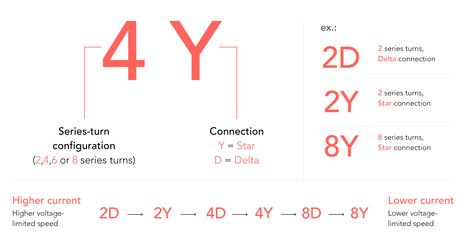
Figure 1 summarizes the winding code nomenclature and the configurations typically available for most motors. 2D represents the lowest-voltage, highest-current end of the range and 8Y the highest-voltage, lowest-current end.
The available configurations depend on the motor size. Larger SlimTorq™ motors are available with 2-, 4- and 8-series-turn options, while some other motor sizes use combinations such as 2 and 6, or 1 and 3 turns.
Want to compare the available winding options? Explore SlimTorq™ and GearTorq™ configurations in our Product Selector.
What Changes With the Number of Series-Turns?
The number of series-turns is the count of individual wire loops connected end-to-end that make up the winding for a given phase in each magnetic pole. This affects both the torque and voltage constant of the motor. Throughout this article, torque constant 𝐾𝑡 follows Alva's catalog convention and is expressed relative to RMS q-axis current. Voltage constant 𝐾𝑒 is based on peak line-to-line back EMF. Other manufacturers may choose to represent these values using a different convention, which may require some calculations to compare.
Within the linear operating range of a permanent-magnet motor, torque is approximately proportional to q-axis current:
T ≈ Kt × Iq
T = Torque [Nm]
Kt = Torque constant [Nm/Arms]
Iq = RMS q-axis current [Arms]
More series-turns increase the torque constant, so less current is required for the same torque. The voltage constant increases approximately the same way as the torque constant. At a given speed, the motor therefore generates more back EMF and therefore uses more of the voltage available from the servo drive to run. This is especially relevant in mid- to high-speed applications. Fewer turns make the opposite exchange: more current is required for torque, but more voltage headroom remains at speed.
Within the same winding family (Delta or Star), line-to-line resistance and inductance scale approximately with the square of the series-turn ratio.
Figure 2 summarizes the design trade-offs involved in selecting the series-turn configuration.
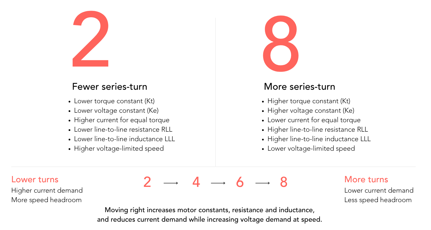
Figure 2: Changes in the characteristics of Alva's electric motors as the number of series-turns in the stator winding increases.
What Is the Difference Between Star and Delta?
Star and Delta describe how the three motor phases are interconnected.
In a Star connection, one end of each phase is joined at a common internal point. In a Delta connection, the phases are connected end-to-end in a closed triangle.
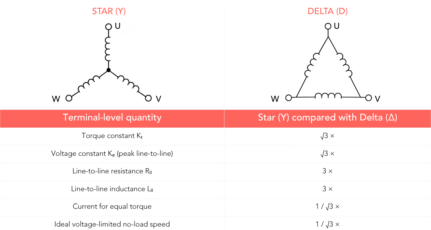
Figure 3: Star and Delta phase connections and their effect on terminal-level motor parameters.
For the same underlying phase winding, and using the same line-level current and voltage conventions:
- Kt and Ke in Star are approximately √3 times their Delta values.
- Line-to-line resistance and inductance in Star are approximately three times their Delta values.
- The current required for the same torque in Star is approximately 1/√3 of the Delta current.
- The no-load speed at the same terminal voltage is approximately 1/√3 of the Delta speed.
Neither connection is inherently better. Star favors a higher-voltage, lower-current operating range. Delta favors a lower-voltage, higher-current operating range.
This is why changing from 2D toward 8Y gradually moves the motor from a high-current, higher-speed electrical interface toward a low-current, lower-speed electrical interface. The right selection is always dependent on the specific application.
A Higher Torque Constant Does Not Necessarily Mean a Stronger Motor
Comparing datasheets for different winding configurations can lead to incorrect conclusions if the highest torque constant, Kt, is used as the sole criterion for selecting the best motor for an application. This selection criterion is incomplete, and the system needs to be analyzed beyond the torque constant alone.
When the number of turns increases, the current required for a given torque decreases, but its winding resistance rises. In the ideal scenario, copper losses at the same torque remain unchanged but this does not include inverter losses, cable losses or speed-dependent motor losses:
Pcu ∝ I²R
If current is halved and resistance becomes four times higher, I²R remains the same. A higher-turn winding does not automatically provide more copper-loss-limited torque or better motor efficiency.
The motor constant therefore remains unchanged across winding variants of the same motor geometry. With Alva’s line-to-line resistance and RMS q-axis current convention, the motor constant is:
Km = Kt / √(3/2 × RLL)
The electrical time constant also remains unchanged because inductance and resistance scale in the same way:
τ = LLL / RLL
This is why the SlimTorq™ catalog states one motor constant and one electrical time constant for the different winding options of a given motor variant. The winding changes the voltage-current interface, not the underlying electromagnetic size of the motor.
At system level, the winding choice can still affect efficiency. Lower current can reduce cable losses and conduction losses in the inverter. A lower Ke can preserve voltage headroom at speed. The motor, drive, cables and power supply must therefore be evaluated as one system.
A Practical Example: STM-75-20-L
The two extremes of the winding configuration options for Alva's SlimTorq™ STM-75-20-L - 2D and 8Y - clearly illustrate this trade-off, as shown in Figure 4.
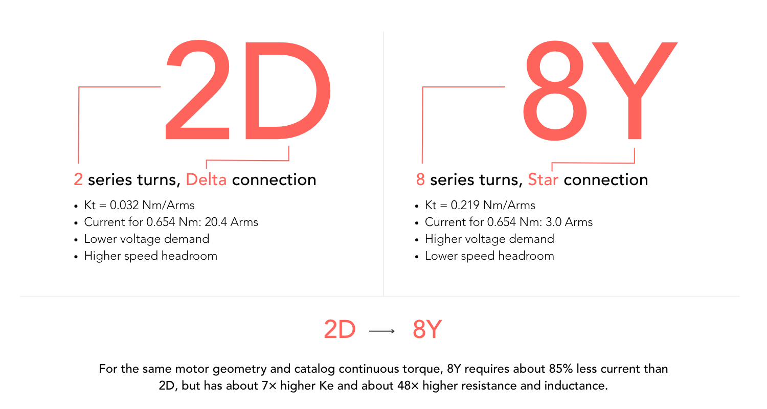
Figure 4: Extreme ends of the winding configurations of STM-75-20-L and its specifications.
The 8Y winding produces the same catalog continuous torque with approximately 85% less current than required by 2D. At the same time, its Ke is about seven times higher, while resistance and inductance are approximately 48 times higher.
The required current can also be estimated directly from Kt:
2D: 0.654 Nm / 0.032 Nm/Arms ≈ 20.4 Arms
8Y: 0.654 Nm / 0.219 Nm/Arms ≈ 3.0 Arms
The 8Y configuration is therefore well suited when the application is current-limited and operates at moderate speed. The 2D configuration is more suitable when the available voltage is low, the drive can supply high current, or a higher-turn winding would become voltage-limited at the required speed.
Want to evaluate your own operating requirements? Explore motor performance for your application in TorqStudio.
How Does Winding Configuration Affect Servo Drive Selection?
Winding configurations should always be selected with the intended servo drive in mind.
Current at the Required Torque
Within the linear operating range, the approximate RMS q-axis current is:
Iq ≈ T / Kt
Both continuous and peak operating points must be checked. The drive must supply the required current for the specified duration and under its own thermal, cooling and switching-frequency conditions.
The current convention must also match the datasheet. Arms, Apeak, phase current and DC-bus current are not interchangeable. SlimTorq™ Kt values are based on RMS q-axis current.
Voltage at the Required Speed
At speed, the drive must overcome the motor’s back EMF as well as resistive and inductive voltage drops. It must also retain voltage margin for inverter modulation and current control.
The required motor voltage is a vector combination of back EMF and the resistive and inductive voltage components. Ke multiplied by speed should therefore not be compared directly with the nominal DC-bus voltage unless the peak/RMS, phase/line and inverter-modulation conventions are handled consistently.
A higher number of series-turns or a Star winding can meet the torque requirement with little current and still fail at maximum speed because the drive does not supply enough voltage. Fewer series-turns or Delta winding can have ample voltage headroom and still fail because the required current exceeds the drive rating.
Resistance must also be evaluated at the expected operating temperature. Copper resistance rises as the stator becomes hotter. The Alva product catalog specifies the resistance at 20°C and excludes the motor cables, and therefore hot winding resistance and cable voltage drop should be included in the final system model.
Inductance and Switching Frequency
SlimTorq™ motors are slotless and can have low inductance, particularly in low-turn Delta configurations. The motor drive must be capable of regulating current without excessive current ripple.
Alva generally recommends high switching frequencies for SlimTorq™ motors. An output filter can be used to add system inductance where required, although its suitability and design must be evaluated for the specific application. Because SlimTorq™ motors have an almost sinusoidal back EMF, sinusoidal commutation or field-oriented control is recommended for the best precision and performance.
How to Select the Correct Winding Configuration?
When selecting a winding configuration for an existing servo drive, the available current and required speed are key considerations. The correct winding configuration leaves both enough current capacity at the required torque and enough voltage headroom at the required speed.
.png)
A practical selection process is:
- Define the complete operating envelope: continuous torque, peak torque and duration, maximum speed, duty cycle and cooling conditions.
- Define the electrical limits: usable DC-bus voltage, continuous and peak drive current, switching frequency and cable length.
- Locate the toughest operating point in terms of power need (high torque and high speed), pick the winding option that can handle this operation with the drive limitations, and with some margin.
- Verify the required current at each torque point using the torque constant Kt from the datasheet and its stated current convention, with some margin for losses.
- Verify the voltage requirement at maximum speed using Ke, hot resistance, inductance, cable drop and sufficient control margin.
A useful starting point is to select the highest-Kt winding, that still reaches the required maximum speed with sufficient voltage margin and remains compatible with the drive’s current-control capability. This often minimizes system current without unnecessarily restricting speed, but the final choice must be validated at system level.
In general, low-speed or current-limited systems tend to favor more series-turns and Star-windings. High-speed, low-voltage or voltage-limited systems tend to favor fewer series-turns and Delta-windings. Intermediate configurations such as 4D or 4Y balance the two and can be useful for more dynamic applications that require both high speeds and low current draws.
Winding Flexibility With FiberPrinting™
Alva’s FiberPrinting™ technology enables precise, non-skewed, ironless and slotless stator windings with a high copper fill factor. It allows SlimTorq™ and GearTorq™ motors to be offered with several standard winding configurations and supports custom configurations when the standard range does not match the application.
The slotless architecture keeps torque proportional to current over a wide operating range without the conventional stator-tooth saturation mechanism found in slotted motors. Thermal, voltage, current, mechanical-speed and magnet-temperature limits still define the practical operating envelope.
Final Thoughts
Different winding configurations are not different power classes. They are different electrical characteristics of the same mechanical motor.
The correct choice is therefore not the winding configuration with the highest torque constant or the highest catalog speed. It is the winding that allows the complete motor-drive-thermal system to meet every required operating point with sufficient margin.
Explore SlimTorq™ and GearTorq™ configurations in Alva’s Product Selector or analyze the complete operating envelope in TorqStudio. For support with winding and drive selection, contact us at sales@alvaindustries.com or book a direct meeting with Alva here.

All rights reserved ©2026