Integration rahmenloser Motoren mit Getrieben: Designmethoden für kompakte Getriebeaktuatoren
Learn how integrating frameless slotless motors with different gear topologies enables more compact, torque-dense actuators. This guide explores planetary, strain wave, cycloidal, and ball screw systems, along with the key engineering considerations for designing high-performance motion systems.
August 20, 2026
When designing a motion control application, engineers must navigate a complex web of specifications and constraints. While application requirements dictate the necessary speed and torque, physical boundaries are strictly defined by volume, weight, and size limitations. Minimizing component count is always ideal to reduce both complexity and cost; however, direct-drive solutions eventually reach a physical threshold where they become too large to deliver the required torque.
This is where gearing becomes relevant. Integrating a gearbox multiplies the motor's output torque, eliminating the need for a larger, heavier motor. Although this trade-off reduces output speed, it is a highly acceptable compromise for many applications. Designing with a frameless motor already requires navigating intricate technical decisions, and introducing a gear stage increases that complexity. Nevertheless, by approaching the integration of these components systematically, engineers can successfully develop a highly efficient, compact, and extremely torque-dense system.
Evolution of Compact Motion Control - Why does it matter now?
The evolution of compact motion control is rapidly accelerating toward extreme miniaturization without sacrificing performance. Across high-stake industries -including robotics, medical devices, and aerospace - the demand for smaller, lighter, and highly integrated systems has reached an all-time high and it does not seem to reach a peak any time soon. To meet these stringent requirements, design engineers are shifting away from bulky, traditionally housed motors towards frameless alternatives.
Consisting solely of a separate rotor and stator, frameless motors integrate directly into a machine’s mechanical structure, such as a robotic joint or surgical tool. This direct integration eliminates redundant components like couplings, bearings, and auxiliary housings, drastically reducing both the system's overall footprint and its mass. In line with this, the industry's primary focus has been on maximizing torque density - delivering the absolute highest torque possible within the smallest available spatial envelope.
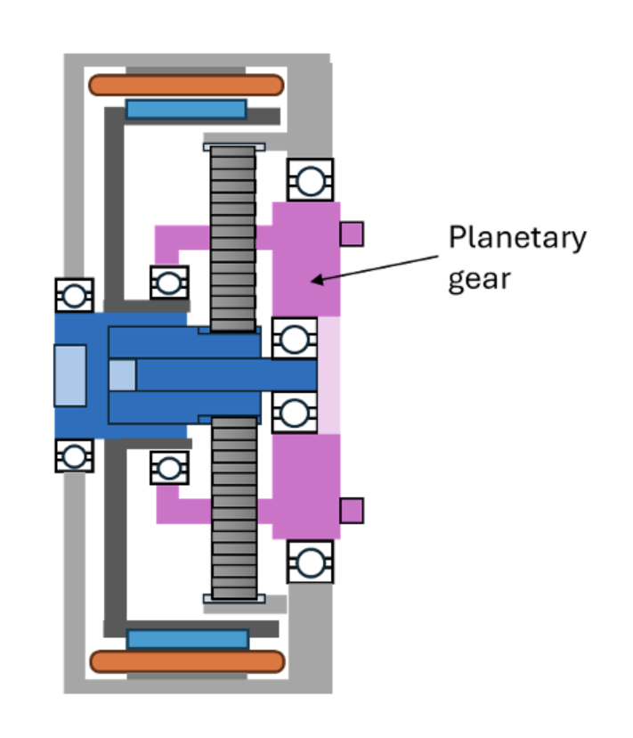
Figure 1. Schematic of a serial “stacked” configurations vs outrunner configuration vs inrunner slotless integration with a planetary gearbox
Combination of a Slotless Frameless Motor with Gears - New Possibilities
Even until now the space and mass savings of integrating a frameless motor, to make actuators more compact and lighter, were quite significant. Using a frameless motor and gearbox, integrated in series, increases complexity and the balance between the savings and the overall complication seems to pay off only in selected cases.
The evolution of compact motion control has achieved a powerful synergy by pairing large inner-diameter motors with centrally integrated gearing. The core advantage of this architecture lies in its radical efficiency of space usage. Eliminating the conventional "stacked" configuration - where the motor sits axially behind the gearhead - dramatically reduces the actuator's overall length and weight of the system. This has traditionally been realized with slotted out-runners, with strong challenges related to thermal dissipation and integration complexity.
This is where the FiberPrinting™ process plays an important role. This revolutionary method of producing ironless and slotless copper windings generates a super compact stator with high fill factor. This stator is then paired with a Halbach array rotor to result in a frameless motor with superior torque density, that can even compete with slotted counterparts. The result is now a super thin in-runner frameless motor that allows for an integration of gearboxes inside the frameless motor. This not only allows for a super compact and light actuator, but due to the nature of a slotless motor design, many other features come along (zero cogging, torque linearity, no torque saturation etc), while keeping the same performance. Furthermore, Alva’s slotless motors do not suffer from magnetic saturation, enabling them to reliably deliver the high peak torques required for dynamic load cases. And lastly, since Alva’s motors are in-runners, the stator sits on the outside which is beneficial for packaging and thermal aspects.
Gear alternatives
The selection of a specific gear topology to pair with a frameless motor depends heavily on the overarching system requirements. Because different gearing technologies offer distinct advantages and trade-offs, the optimal choice is dictated by the specific needs of the application. Here is an overview of the primary gearing alternatives typically utilized in these designs.
Planetary
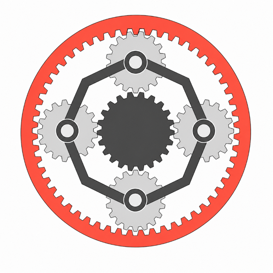
A planetary gear is an epicyclic gearing system consisting of a central input gear (the sun gear) surrounded by orbiting driven gears (planet gears) that interface with an outer ring gear. Depending on the required reduction ratio, the system can be configured as a single stage or stacked into multiple stages.
Advantages:
- High Torsional Stiffness & Load Distribution: Because the mechanical load is distributed across multiple planet gears simultaneously, the system exhibits exceptional torsional stiffness.
- Shock Load Resilience: This load-sharing architecture allows planetary gears to withstand sudden shock loads effectively.
- High Efficiency & Torque Density: They can be engineered to deliver excellent torque density alongside high high-speed efficiency.
Limitations:
- Backlash: Planetary systems inherently suffer from mechanical backlash, which can impact precision.
- Axial Length: Achieving higher gear ratios requires stacking multiple stages, which increases the overall axial length of the actuator.
Typical Applications:
Planetary gears are widely utilized in for example aerospace actuators, humanoid robotics, Automated Guided Vehicles (AGVs), and high-speed pick-and-place systems.
Traditional Planetary gear and Motor combinations:
Typically, an actuator made with Planetary gears delivers high speed, torque density, and back-drivability. However, it suffers from mechanical backlash, and stacking stages for higher torque increases axial length, requiring secondary feedback for ultra-precision.
New possibilities for Planetary gear actuators with Thin section motors:
With Alva's thin section motors, the gear’s axial length is mitigated by the compact shape and large inner bore, that allows the gear to be placed in the motor’s centre. The slotless design eliminates cogging to ensure ultra-smooth rotation and optimizes the high-speed efficiency. And the large peak torque capabilities allow for reduced gear-ratios and increased back-driveability for the actuator.
Strain wave (Harmonic drives)
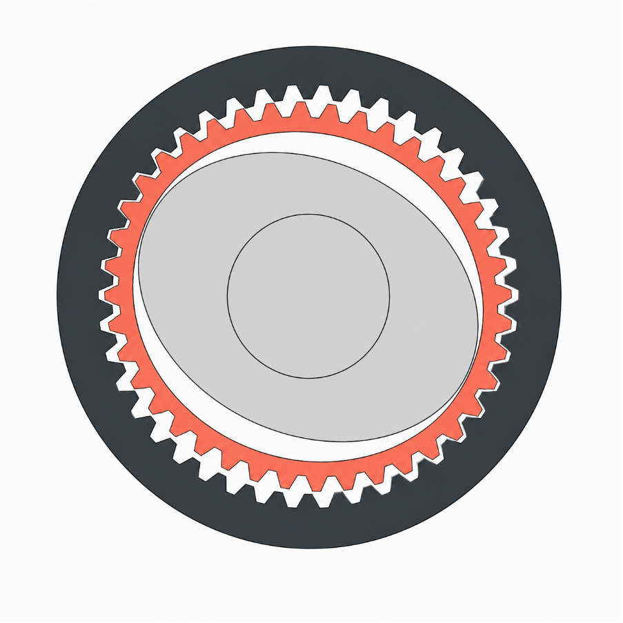
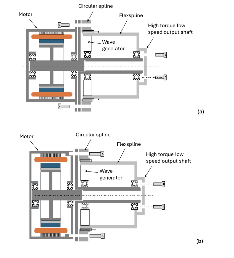
A strain wave gear consists of three core components: an elliptical wave generator, a flexible splined cup with external teeth (flexspline), and a rigid outer ring gear (circular spline). As the wave generator rotates inside the flexible cup, it deforms it to engage with the outer ring gear. This unique mechanism creates a highly compact, single-stage system capable of achieving exceptionally high reduction ratios.
Advantages:
- Near-Zero Backlash: Because multiple gear teeth remain in continuous contact simultaneously, strain wave gears exhibit minimal to near-zero backlash, making them ideal for high-precision applications.
- High Single-Stage Ratios: It’s possible to achieve high gear reduction in a compact single stage footprint.
- Integrated Hollow Bore: In addition to achieving high gear ratios in a single stage, these systems frequently feature a large central hollow bore, allowing for the clean routing of cables and service lines.
Limitations:
- Reduced Stiffness: Due to the inherent flexibility of the internal components, strain wave gears lack the high torsional stiffness found in rigid gearing systems.
- Speed Restrictions: Thermal constraints and the mechanics of the flexible deformation can limit their performance at high input speeds.
Typical Applications:
Strain wave gears are the industry standard for precision robotic joints, surgical robots, and high-accuracy positioning gimbals and some other applications.
Traditional Strain wave gear and Motor combinations:
Typically, an actuator made with Strain wave gears delivers zero backlash, high torque density, and high single-stage reduction ratios in a compact axial footprint. However, it suffers from limited top speeds, torque ripple (velocity error), and high friction that reduces efficiency and limits back-drivability.
New possibilities for Strain wave gear actuators with Thin section motors:
With Alva's thin section motors, the actuator achieves an ultra-flat, pancake form matching the gear’s short axial length. The slotless design eliminates motor cogging to improve output smoothness, minimizes thermal losses at low speeds, and, if required, makes possible a massive hollow shaft for clean, through-bore cabling.
Cycloidal
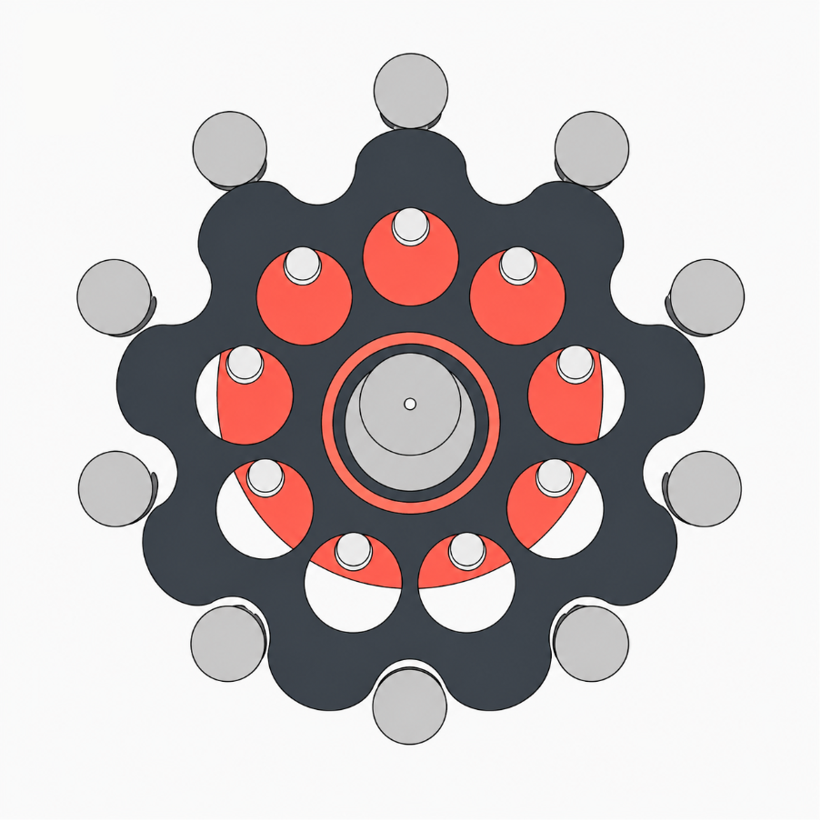
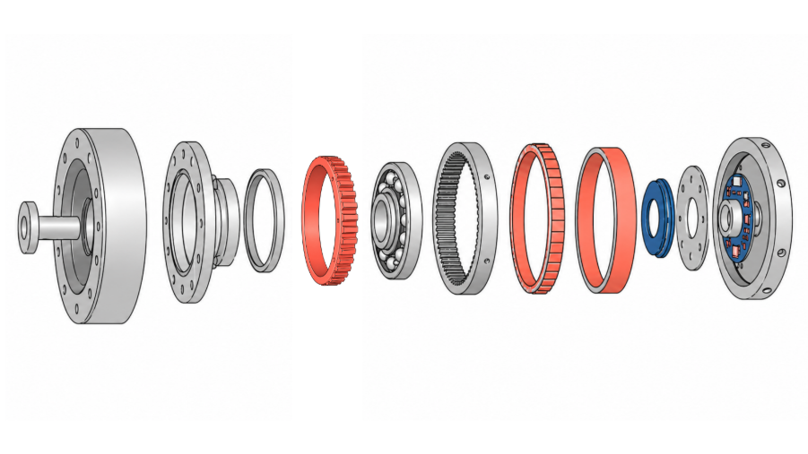
A cycloidal drive consists of an input shaft with an eccentric bearing or cam that drives a series of cycloidal discs. These discs roll inside a stationary ring of pins or rollers, engaging with an output shaft mechanism in a smooth, continuous motion. Because a high percentage of the load-bearing surfaces remain in contact simultaneously, the mechanism achieves exceptional load sharing.
Advantages:
- Superior Shock Load Resistance: The extensive load distribution across multiple contacting elements enables cycloidal gears to withstand extreme shock loads without catastrophic failure.
- High Single-Stage Ratios: They can achieve significant reduction ratios within a compact, single-stage footprint.
- Low Backlash: The rolling contact design inherently minimizes mechanical backlash, ensuring high positioning accuracy.
Limitations:
- Mechanical Complexity: The intricate configuration of eccentric cams, multiple discs, and precision rollers increases manufacturing complexity and component count.
- High-Speed Vibrations: Due to the inherent inertial forces of the eccentric rotating masses, cycloidal drives can suffer from considerable vibration at elevated speeds.
Typical Applications:
Cycloidal gears are ideally suited for high-impact environments, including lower-limb exoskeletons, heavy-duty mobile robotics, and high-precision industrial automation systems.
Traditional Cycloidal gear and Motor combinations:
Typically, an actuator made with Cycloidal gears delivers extreme shock load resilience, high torque density, and minimal backlash within a compact footprint. However, it suffers from internal eccentric vibrations at high speeds, complex manufacturing tolerances, and higher rolling friction that reduces overall efficiency and back-drivability.
New possibilities for Cycloidal gear actuators with Thin section motors:
With Alva's thin section motors, the actuator maintains a highly integrated, ultra-flat profile that mirrors the gear's short axial length. The slotless design eliminates cogging to maximize torque smoothness at low speeds, while the low high-frequency losses help mitigate heat generation when driving the gear's eccentric inputs. The compact motor shape helps to allow for this motor and gear combination even at small physical dimensions as there is more space for the gear.
Ball screws - Rotary to Linear movement
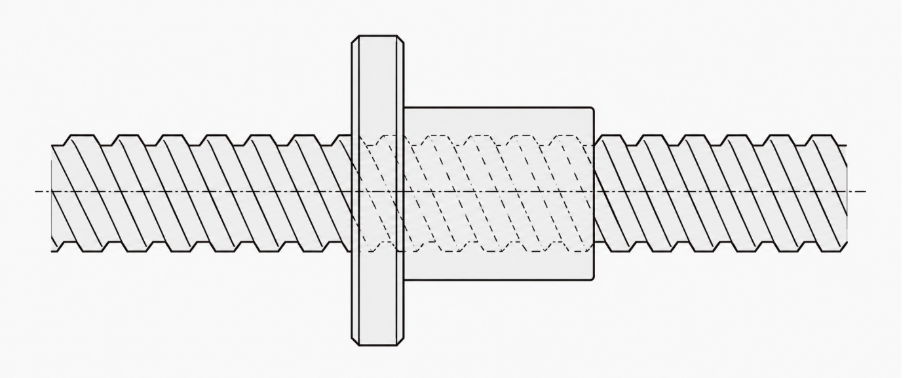
A ball screw is a highly effective mechanical actuator utilized to convert rotary motion from a motor into precise linear motion. The assembly consists of a precision-threaded shaft and a matching nut packed with recirculating ball bearings, which travel along the shaft to drive the linear load.
Advantages:
- High Mechanical Efficiency: Because the system relies on rolling elements rather than sliding friction, it offers exceptional mechanical efficiency and minimal power loss.
- Smooth Motion & Low Friction: The continuous rolling of the bearings ensures smooth, predictable linear translation with minimal stick-slip effect.
Limitations:
- No Centre Through-Bore: Unlike certain rotary gear topologies, ball screws cannot accommodate a hollow bore, which limits options for central cable routing.
- Speed Restrictions (Whip Effect): Long and slender ball screw shafts are susceptible to structural deflection and vibration at elevated speeds - a phenomenon known as screw whip - which places a strict ceiling on maximum velocity.
Typical Applications:
Ball screws are widely integrated into medical infusion pumps, aerospace flight control actuators, and high-precision optical or laser focusing stages.
Traditional Ball screw and Motor combinations:
Typically, an actuator made with Ball screws delivers exceptionally high linear force, precise positioning, and excellent efficiency with near-zero backlash. However, it suffers from limited linear speed, it strictly converts rotary motion to linear movement and requires significant axial length to accommodate the screw travel.
New possibilities for Ball screw actuators with Thin section motors:
With Alva's thin section motors, the actuator achieves an ultra-compact, rotary to linear configuration. The motor’s large hollow shaft allows the ball screw shaft to pass directly through the rotor, drastically reducing overall axial length, while the slotless design eliminates cogging to ensure ultra-smooth, sub-micron linear positioning.
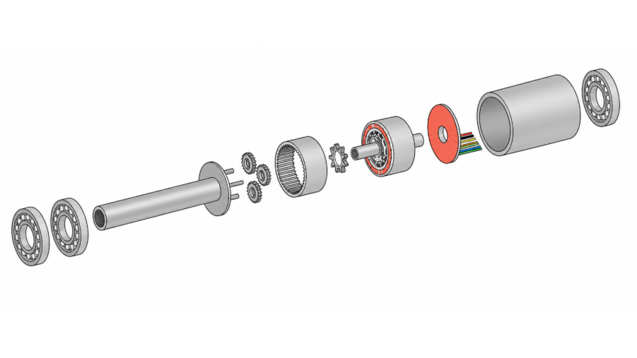
General Key Considerations for the Mechanical Integration
When integrating a frameless motor with a gear set, several engineering and assembly factors must be addressed to ensure optimal actuator performance and long-term durability. The following list outlines the primary integration considerations and highlights key parameters to evaluate during the design phase:
- Air Gap Integrity & Concentricity: Frameless motors are engineered with tight tolerances, often featuring an air gap of only a few tenths of a millimetre. Maintaining absolute concentricity between the rotor and stator across all load scenarios - especially under the complex forces exerted on the gear set - is critical. Consequently, this heavily influences bearing selection and structural component design based on the application's specific load profiles. Furthermore, managing the radial air gap becomes significantly more challenging due to a more complex tolerance stack-up introduced by the increased number of interacting components.
- Thermal Management & Heat Dissipation: Because the gear set is typically integrated centrally within the inner diameter of the rotor, the thermal energy generated by frictional and mechanical losses inside the gearbox directly impacts motor temperatures. Balancing system performance requirements against the motor's operating temperature limits is critical. Specifically, designers must account for the fact that the rotor and its permanent magnets are more thermally sensitive and cannot withstand the same peak temperatures as the stator windings without risking demagnetization or degradation.
- Inertia Matching & Back-driveability: In a geared system, the reflected inertia of the load scales inversely with the square of the gear ratio, meaning the motor perceives the load inertia divided by n2 (wobei n das Untersetzungsverhältnis darstellt). Umgekehrt wird das auf den Ausgang reflektierte Trägheitsmoment des Rotors um den Faktor n² verstärkt.2. Die Optimierung des Trägheitsverhältnisses zwischen Rotor und Last – idealerweise mit einem Zielwert von 1:1 für maximale dynamische Leistung – bei gleichzeitiger Gewährleistung der Rückwärtsantreibbarkeit stellt eine erhebliche konstruktive Herausforderung dar. Das ideale Gleichgewicht hängt stark von den dynamischen Bewegungsprofilen des Systems und dem für die jeweilige Anwendung erforderlichen Grad an Rückwärtsantreibbarkeit ab.
- Vibrationsminderung & Strukturdynamik: Der Einsatz eines Getriebes erhöht systembedingt die akustischen und mechanischen Vibrationsprofile innerhalb eines Bewegungssteuerungssystems. Um diese unerwünschten Harmonischen zu minimieren, ist es entscheidend, dass alle rotierenden Komponenten dynamisch ausgewuchtet und die Gehäusestrukturen mit der erforderlichen Steifigkeit ausgelegt sind. Eine präzise Ausrichtung der Komponenten sowie enge Fertigungstoleranzen sind unerlässlich, um zyklische Anregungen zu minimieren und die Systemstabilität unter Last aufrechtzuerhalten.
- Optimierung der Hohlwelle & Kabelführung: Die zentrale Integration eines Getriebes innerhalb des Rotors schränkt den verfügbaren Durchmesser der Durchgangsbohrung ein. Je nach gewählter Getriebetechnologie lassen sich unterschiedliche Hohlwellendurchmesser realisieren. Wellgetriebe (Strain Wave Gears) bieten in der Regel die besten Voraussetzungen für eine großzügige mittlere Öffnung bei gleichzeitig hohen Untersetzungsverhältnissen. Auch Planetengetriebe können für eine Hohlwelle ausgelegt werden, wobei diese Konfiguration jedoch meist eine höhere mechanische Komplexität bei der internen Leitungsführung durch die umlaufenden Komponenten erfordert.
- Schmierstoffisolierung & Dichtungsintegrität: Wenn das gewählte Getriebe eine Schmierung erfordert, muss diese zuverlässig vom Motorenraum isoliert werden. Ein Eindringen von Schmierstoffen in den engen Luftspalt würde den viskosen Widerstand erhöhen, was zu parasitären Leistungsverlusten und einem sinkenden Wirkungsgrad führt. Zudem können wandernde Schmierstoffe die Isolierung der Statorwicklungen chemisch angreifen – was potenziell zu elektrischen Kurzschlüssen führen kann – während eine defekte Dichtung das Eindringen von Umweltschmutz und Abriebpartikeln in den magnetischen Luftspalt ermöglicht, was abrasive Schäden zur Folge haben kann.
- Dual-Sensor-Feedback & Präzisionssteuerung: Für Anwendungen, die eine hohe Positioniergenauigkeit erfordern, ist der Einsatz eines Dual-Sensor-Feedbacks – mit einem Encoder auf jeder Seite der Getriebestufe – sehr zu empfehlen. Diese Dual-Loop-Konfiguration ermöglicht es dem Steuerungssystem, mechanisches Spiel, Torsionsverformungen und andere im Getriebe inhärente Nichtlinearitäten aktiv zu messen und zu kompensieren.
Anpassungsmöglichkeiten, GearTorq™ und abschließende Schlussfolgerungen
Die Kombination eines rahmenlosen, nutenlosen Motors mit einem korrekt dimensionierten Getriebesystem bietet eine hervorragende Lösung für Anwendungen, die eine hohe Leistungsdichte bei strengen Platz- oder Gewichtsvorgaben erfordern. Die Identifizierung der idealen Kombination aus Standardmotor und -getriebe kann jedoch eine Herausforderung darstellen, da die Paarung fast immer einen Kompromiss zwischen widersprüchlichen Leistungskennzahlen darstellt. Standardkomponenten decken sich selten perfekt in Bezug auf Drehmoment, Drehzahl und thermische Grenzwerte, was Konstrukteure oft dazu zwingt, suboptimale Wirkungsgrade oder überdimensionierte Gehäuse in Kauf zu nehmen. Die Nutzung einer anpassbaren Motorplattform löst diesen Engpass und ermöglicht es Ingenieuren, die Wicklung und die physische Geometrie des Motors präzise auf die einzigartigen Eigenschaften des Getriebes abzustimmen und die Gesamtleistung des Systems zu optimieren.
FiberPrinting™ ist ein flexibles Fertigungsverfahren, das eine individuelle Anpassung des Motors ermöglicht. Dies bedeutet, dass Ingenieure einen optimierten Aktuator entwerfen können, der auf den Anwendungsanforderungen und -beschränkungen basiert und die verfügbaren Getriebealternativen bereits berücksichtigt – und nicht umgekehrt. Dies eröffnet alle denkbaren Lösungswege und ermöglicht die beste Wahl für jedes Projekt.
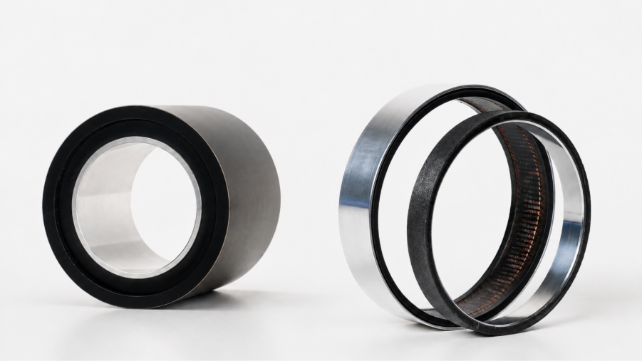
Alva bietet zudem die GearTorq™ Produktlinie an, die im Vergleich zur SlimTorq™ längere Motoren umfasst. Bereich. Bei gleichem kompakten Formfaktor und großem Innendurchmesser GearTorq™ Motoren können mit verschiedenen Getriebetopologien kombiniert werden, die zentral im Motor platziert sind. Da die meisten Getriebesätze eine gewisse Baulänge hinzufügen, wird dieser verfügbare Raum durch etwas längere Motoren optimal genutzt.
Wenn Sie ein System entwickeln und mögliche Lösungen mit unserem Team besprechen möchten, kontaktieren Sie uns bitte hier.

Alle Rechte vorbehalten ©2025